A selection of simple and effective schemes. Multivibrators on transistors Multivibrator on transistors diagram operating principle
LED flasher or how to assemble a symmetrical multivibrator with your own hands. The circuit of a symmetrical multivibrator must be studied and collected in electronics clubs. The multivibrator circuit is one of the most famous and often used in various electronic designs. A symmetrical multivibrator during operation generates oscillations in shape approaching rectangular. The simplicity of the multivibrator is due to its design - it is only two transistors and several additional elements. The wizard invites you to assemble your first electronic LED flasher circuit. In order not to be disappointed in case of failure, below are detailed step-by-step instructions for assembling a multivibrator LED flasher with photo and video illustrations.
How to assemble an LED flasher with your own hands
A little theory. A multivibrator is essentially a two-stage amplifier on transistors VT1 and VT2 with a positive feedback circuit through an electrolytic capacitor C2 between the amplification stages on transistors VT2 and VT1. This feedback turns the circuit into an oscillator. The name symmetrical multivibrator is due to the same values of the pairs of elements R1=R2, R3=R4, C1=C2. With such values of the elements, the multivibrator will generate pulses and pauses between pulses of equal duration. The pulse repetition rate is set to a greater extent by the values of the pairs R1=R2 and C1=C2. The duration of pulses and pauses can be controlled by LED flashes. If the equality of pairs of elements is violated, the multivibrator becomes asymmetrical. The asymmetry will be due primarily to the difference in the duration of the pulse and the duration of the pause.
The multivibrator is assembled on two transistors; in addition, four resistors, two electrolytic capacitors and two LEDs are required to indicate the operation of the multivibrator. The task of purchasing parts and a printed circuit board is easily solved. Here is a link to purchase a ready-made set of parts http://ali.pub/2bk9qh . The kit includes all parts, a good quality 28mm x 30mm printed circuit board, schematic, wiring diagram and specification sheet. There are practically no errors in the location of parts on the printed circuit board drawing.
Composition of the multivibrator parts kit
Let's start assembling the circuit; for work you will need a low-power soldering iron, soldering flux, solder, side cutters and batteries. The circuit is simple, but it must be assembled correctly and without errors.
- Review the contents of the package. Decipher the resistor values by color code and install them on the board.
- Solder the resistors and bite off the protruding remains of the electrodes.
- Electrolytic capacitors must be placed in a specific way on the board. The wiring diagram and drawing on the board will help you with the correct placement. Electrolytic capacitors are marked on the body with a negative electrode, and the positive electrode is slightly longer. The location of the negative electrode on the board is in the shaded part of the capacitor symbol.
- Place the capacitors on the board and solder them.
- The placement of transistors on the board is strictly according to the key.
- LEDs also have electrode polarity. See photo. We install and solder them. Be careful not to overheat this part when soldering. The plus of LED2 is located closer to resistor R4 (see video).
LEDs are installed on the multivibrator board
- Solder the power conductors according to the polarity and apply voltage from the batteries. At a supply voltage of 3 Volts, the LEDs turned on together. After a moment of disappointment, voltage from three batteries was applied and the LEDs began to blink alternately. The frequency of the multivibrator depends on the supply voltage. Since the circuit was to be installed in a toy powered by 3 Volts, resistors R1 and R2 had to be replaced with resistors rated 120 kOhm, and clear alternating blinking was achieved. Watch the video.
LED flasher - symmetrical multivibrator
The application of the symmetrical multivibrator circuit is very wide. Elements of multivibrator circuits are found in computer technology, radio measuring and medical equipment.
A set of parts for assembling LED flashers can be purchased at the following link http://ali.pub/2bk9qh . If you want to seriously practice soldering simple structures, the Master recommends purchasing a set of 9 sets, which will greatly save your shipping costs. Here is the link to purchase http://ali.pub/2bkb42 . The master collected all the sets and they started working. Success and growth of skills in soldering.
The multivibrator is perhaps the most popular device among beginner radio amateurs. And recently I had to put one together at the request of one person. Although I’m no longer interested in this, I still wasn’t lazy and compiled the product into an article for beginners. It’s good when one material contains all the information for assembly. a very simple and useful thing that does not require debugging and allows you to visually study the principles of operation of transistors, resistors, capacitors and LEDs. And also, if the device does not work, try yourself as a regulator-debugger. The scheme is not new, it is built according to a standard principle, and the parts can be found anywhere. They are very common.
Scheme
Now what do we need from radioelements for assembly:
- 2 resistors 1 kOhm
- 2 resistors 33 kOhm
- 2 capacitors 4.7 uF at 16 volts
- 2 KT315 transistors with any letters
- 2 LEDs for 3-5 volts
- 1 crown power supply 9 volt
If you couldn't find the parts you needed, don't worry. This circuit is not critical to the ratings. It is enough to set approximate values; this will not affect the work as a whole. It only affects the brightness and blinking frequency of the LEDs. The blinking time directly depends on the capacitance of the capacitors. Transistors can be installed in similar low-power n-p-n structures. We make a printed circuit board. The size of a piece of textolite is 40 by 40 mm, you can take it with a reserve.

Printable file format. lay6 download. In order to make as few mistakes as possible during installation, I applied positional designations to the textolite. This helps avoid confusion during assembly and adds beauty to the overall look. This is what the finished printed circuit board looks like, etched and drilled:

We install the parts in accordance with the diagram, this is very important! The main thing is not to confuse the pinout of transistors and LEDs. Soldering should also be given due attention.

At first it may not be as elegant as an industrial one, but it doesn’t need to be. The main thing is to ensure good contact of the radio element with the printed conductor. To do this, we must tin the parts before soldering. After the components are installed and soldered, we check everything again and wipe the rosin off the board with alcohol. The finished product should look something like this:

If everything was done correctly, then when power is applied, the multivibrator begins to blink. You choose the color of the LEDs yourself. For clarity, I suggest watching the video.
Multivibrator video
The current consumption of our “flashing lights” is only 7.3 mA. This allows this instance to be powered from " crowns"for quite a long time. In general, everything is trouble-free and informative, and most importantly, extremely simple! I wish you well and success in your endeavors! Prepared by Daniil Goryachev ( Alex1).
Discuss the article SYMMETRICAL MULTIVIBRATOR FOR LEDS
Electronic generators: multivibrator. Purpose, principle of operation, application.
Multivibrators
The multivibrator is a relaxation oscillator of almost rectangular shape. It is a two-stage resistor amplifier with positive feedback, in which the output of each stage is connected to the input of the other. The name “multivibrator” itself comes from two words: “multi” - many and “vibrator” - a source of oscillations, since the oscillations of a multivibrator contain a large number of harmonics. The multivibrator can operate in self-oscillating mode, synchronization mode and standby mode. In the self-oscillating mode, the multivibrator operates as a self-excited oscillator; in the synchronization mode, the multivibrator is acted upon externally by a synchronizing voltage, the frequency of which determines the pulse frequency; and in standby mode, the multivibrator operates as a generator with external excitation.
Multivibrator in self-oscillating mode
Figure 1 shows the most common circuit of a multivibrator based on transistors with capacitive collector-base connections, and Figure 2 shows graphs explaining the principle of its operation. The multivibrator consists of two amplification stages on resistors. The output of each stage is connected to the input of the other stage through connectors C1 and C2.
Rice. 1 - Multivibrator based on transistors with capacitive collector-base connections
A multivibrator in which the transistors are identical and the parameters of the symmetrical elements are the same is called symmetrical. Both parts of the period of its oscillations are equal and the duty cycle is 2. If anyone has forgotten what duty cycle is, I remind you: duty cycle is the ratio of the repetition period to the pulse duration Q = T and /t and. The reciprocal of the duty cycle is called the duty cycle. So, if there are differences in the parameters, then the multivibrator will be asymmetrical.
A multivibrator in a self-oscillating mode has two quasi-equilibrium states, when one of the transistors is in saturation mode, the other in cutoff mode, and vice versa. These conditions are not stable. The transition of the circuit from one state to another occurs like an avalanche due to the deep PIC.

Rice. 2 - Graphs explaining the operation of a symmetrical multivibrator
Let's say that when the power is turned on, transistor VT1 is open and saturated with current passing through resistor R3. The voltage on its collector is minimal. Condenser C1 is discharged. Transistor VT2 is closed and capacitor C2 is charging. The voltage at conductor C1 tends to zero, and the potential at the base of transistor VT2 gradually becomes positive and VT2 begins to open. The voltage at its collector decreases and capacitor C2 begins to discharge, transistor VT1 closes. The process is then repeated ad infinitum.
The circuit parameters should be as follows: R1=R4, R2=R3, C1=C2. The pulse duration is determined by the formula:
The pulse period is determined:
Well, to determine the frequency, you need to divide one by this crap (see just above).
The output pulses are taken from the collector of one of the transistors, and from which one it does not matter. In other words, there are two outputs in the circuit.
Improving the shape of the multivibrator output pulses removed from the transistor collector can be achieved by including isolation (disconnecting) diodes in the collector circuits, as shown in Figure 3. Additional resistors R d1 and R d2 are connected through these diodes in parallel with the collector loads.

Rice. 3 - Multivibrator with improved output pulse shape
In this circuit, after one of the transistors is closed and the collector potential is lowered, the diode connected to its collector also closes, disconnecting the condenser from the collector circuit. The charge of the condenser occurs through an additional resistor Rd, and not through a resistor in the collector circuit, and the collector potential of the turn-off transistor almost abruptly becomes equal to Ec. The maximum duration of the pulse fronts in the collector circuits is determined mainly by the frequency properties of the transistors.
This scheme makes it possible to obtain pulses of almost rectangular shape, but its disadvantages are a lower maximum duty cycle and the impossibility of smoothly adjusting the oscillation period.
Figure 4 shows a circuit of a high-speed multivibrator that provides a high frequency of self-oscillations.

Rice. 4 - High-speed multivibrator
In this circuit, the resistors R2, R4 are connected in parallel to the capacitors C1 and C2, and the resistors R1, R3, R4, R6 form voltage dividers that stabilize the base potential of the open transistor (when the divider current is greater than the base current). When the multivibrator is switched, the base current of the saturated transistor changes more sharply than in the previously discussed circuits, which reduces the time of resorption of charges in the base and accelerates the transistor's exit from saturation.
Waiting multivibrator
A multivibrator operating in a self-oscillating mode and not having a state of stable equilibrium can be turned into a multivibrator having one stable position and one unstable position. Such circuits are called standby multivibrators or single-shot multivibrators, single-pulse multivibrators, relaxation relays or kipp relays. The circuit is transferred from a stable state to an unstable state by the action of an external trigger pulse. The circuit remains in an unstable position for some time, depending on its parameters, and then automatically, abruptly returns to its original stable state.
To obtain a standby mode in a multivibrator, the circuit of which was shown in Fig. 1, you need to throw out a couple of parts and replace them, as shown in Fig. 5.

Rice. 5 - Waiting multivibrator
In the initial steady state, transistor VT1 is closed. When a positive trigger pulse of sufficient amplitude arrives at the input of the circuit, a collector current begins to flow through the transistor. The change in voltage at the collector of transistor VT1 is transmitted through capacitor C2 to the base of transistor VT2. Thanks to the PIC (through resistor R4), an avalanche-like process increases, leading to the closing of transistor VT2 and the opening of transistor VT1. The circuit remains in this state of unstable equilibrium until capacitor C2 is discharged through resistor R2 and conducting transistor VT1. After the discharge of the condenser, transistor VT2 opens, and VT1 closes and the circuit returns to its original state.
Blocking generators
The blocking oscillator is a single-stage relaxation generator of short-term pulses with strong inductive positive feedback created by a pulse transformer. The pulses generated by the blocking generator have a large rise and fall steepness and are close to rectangular in shape. The pulse duration can range from several tens of ns to several hundreds of microseconds. Typically, the blocking generator operates in high duty cycle mode, i.e., the duration of the pulses is much less than their repetition period. The duty cycle can be from several hundred to tens of thousands. The transistor on which the blocking generator is assembled opens only for the duration of the pulse generation, and is closed the rest of the time. Therefore, with a large duty cycle, the time during which the transistor is open is much less than the time during which it is closed. The thermal regime of the transistor depends on the average power dissipated at the collector. Due to the high duty cycle in the blocking oscillator, very high power can be obtained during low and medium power pulses.
With a high duty cycle, the blocking oscillator operates very economically, since the transistor consumes energy from the power source only during a short pulse formation time. Just like a multivibrator, a blocking oscillator can operate in self-oscillating, standby, and synchronization modes.
Self-oscillating mode
Blocking generators can be assembled using transistors connected in a circuit with an OE or in a circuit with an OB. The circuit with OE is used more often, since it allows one to obtain a better shape of the generated pulses (shorter rise time), although the circuit with OB is more stable with respect to changes in the parameters of the transistor.
The blocking oscillator circuit is shown in Fig. 1.

Rice. 1 - Blocking generator
The operation of the blocking generator can be divided into two stages. In the first stage, which occupies most of the oscillation period, the transistor is closed, and in the second, the transistor is open and a pulse is formed. The closed state of the transistor in the first stage is maintained by the voltage on capacitor C1, charged by the base current during the generation of the previous pulse. In the first stage, the condenser is slowly discharged through the high resistance of the resistor R1, creating a potential close to zero at the base of the transistor VT1 and it remains closed.
When the voltage at the base reaches the opening threshold of the transistor, it opens and current begins to flow through the collector winding I of transformer T. In this case, a voltage is induced in the base winding II, the polarity of which must be such that it creates a positive potential at the base. If windings I and II are connected incorrectly, the blocking oscillator will not generate. It means that the ends of one of the windings, no matter which one, must be swapped.
MULTIVIBRATOR
Multivibrator. I’m sure many people started their amateur radio activities with this scheme.This was also my first diagram - a piece of plywood, holes punched with nails, the leads of the parts were twisted with wire in the absence of a soldering iron.And everything worked great!
LEDs are used as a load. When the multivibrator is working, the LEDs switch.
Assembly requires a minimum of parts. Here is the list:
- - Resistors 500 Ohm - 2 pieces
- - Resistors 10 kOhm - 2 pieces
- - Electrolytic capacitor 1 uF for 16 volts - 2 pieces
- - Transistor KT972A - 2 pieces (KT815 or KT817 will also work), KT315 is also possible, if the current is no more than 25mA.
- - LED - any 2 pieces
- - Power supply from 4.5 to 15 volts.
The figure shows one LED in each channel, but several can be connected in parallel. Or in series (a chain of 5 pieces), but then the power supply is not less than 15 volts.
KT972A transistors are composite transistors, that is, their housing contains two transistors, and it is highly sensitive and can withstand significant current without heat sink.
To conduct experiments, you don’t need to make a printed circuit board; you can assemble everything using a surface-mounted installation. Solder as shown in the pictures.
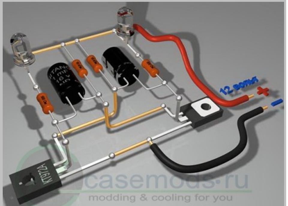
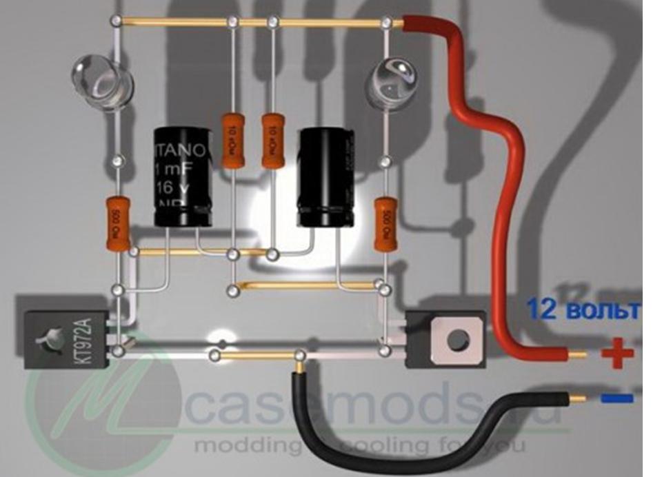
The drawings are specially made from different angles and you can examine in detail all the details of the installation.
In this article we will talk about the multivibrator, how it works, how to connect a load to the multivibrator and the calculation of a transistor symmetrical multivibrator.
Multivibrator is a simple rectangular pulse generator that operates in self-oscillator mode. To operate it, you only need power from a battery or other power source. Let's consider the simplest symmetrical multivibrator using transistors. Its diagram is shown in the figure. The multivibrator can be more complicated depending on the necessary functions performed, but all the elements presented in the figure are mandatory, without them the multivibrator will not work.
The operation of a symmetrical multivibrator is based on the charge-discharge processes of capacitors, which together with resistors form RC circuits.
I wrote earlier about how RC circuits work in my article Capacitor, which you can read on my website. On the Internet, if you find material about a symmetrical multivibrator, it is presented briefly and not intelligibly. This circumstance does not allow novice radio amateurs to understand anything, but only helps experienced electronics engineers remember something. At the request of one of my site visitors, I decided to eliminate this gap.
How does a multivibrator work?

At the initial moment of power supply, capacitors C1 and C2 are discharged, so their current resistance is low. The low resistance of the capacitors leads to the “fast” opening of the transistors caused by the flow of current:
— VT2 along the path (shown in red): “+ power supply > resistor R1 > low resistance of discharged C1 > base-emitter junction VT2 > — power supply”;
— VT1 along the path (shown in blue): “+ power supply > resistor R4 > low resistance of discharged C2 > base-emitter junction VT1 > — power supply.”
This is the “unsteady” mode of operation of the multivibrator. It lasts for a very short time, determined only by the speed of the transistors. And there are no two transistors that are absolutely identical in parameters. Whichever transistor opens faster will remain open—the “winner.” Let's assume that in our diagram it turns out to be VT2. Then, through the low resistance of the discharged capacitor C2 and the low resistance of the collector-emitter junction VT2, the base of the transistor VT1 will be short-circuited to the emitter VT1. As a result, transistor VT1 will be forced to close - “become defeated”.

Since transistor VT1 is closed, a “fast” charge of capacitor C1 occurs along the path: “+ power supply > resistor R1 > low resistance of discharged C1 > base-emitter junction VT2 > — power supply.” This charge occurs almost up to the voltage of the power supply.
At the same time, capacitor C2 is charged with a current of reverse polarity along the path: “+ power supply > resistor R3 > low resistance of discharged C2 > collector-emitter junction VT2 > — power source.” The charge duration is determined by the ratings R3 and C2. They determine the time at which VT1 is in the closed state.

When capacitor C2 is charged to a voltage approximately equal to the voltage of 0.7-1.0 volts, its resistance will increase and transistor VT1 will open with the voltage applied along the path: “+ power supply > resistor R3 > base-emitter junction VT1 > - power supply.” In this case, the voltage of the charged capacitor C1, through the open collector-emitter junction VT1, will be applied to the emitter-base junction of transistor VT2 with reverse polarity. As a result, VT2 will close, and the current that previously passed through the open collector-emitter junction VT2 will flow through the circuit: “+ power supply > resistor R4 > low resistance C2 > base-emitter junction VT1 > — power supply.” This circuit will quickly recharge capacitor C2. From this moment, the “steady-state” self-generation mode begins.
Operation of a symmetrical multivibrator in “steady-state” generation mode
The first half-cycle of operation (oscillation) of the multivibrator begins.

When transistor VT1 is open and VT2 is closed, as I just wrote, capacitor C2 is quickly recharged (from a voltage of 0.7...1.0 volts of one polarity, to the voltage of the power source of the opposite polarity) along the circuit: “+ power supply > resistor R4 > low resistance C2 > base-emitter junction VT1 > - power supply.” In addition, capacitor C1 is slowly recharged (from the power source voltage of one polarity to a voltage of 0.7...1.0 volts of the opposite polarity) along the circuit: “+ power source > resistor R2 > right plate C1 > left plate C1 > collector- emitter junction of transistor VT1 > - - power source.”
When, as a result of recharging C1, the voltage at the base of VT2 reaches a value of +0.6 volts relative to the emitter of VT2, the transistor will open. Therefore, the voltage of the charged capacitor C2, through the open collector-emitter junction VT2, will be applied to the emitter-base junction of the transistor VT1 with reverse polarity. VT1 will close.
The second half-cycle of operation (oscillation) of the multivibrator begins.

When transistor VT2 is open and VT1 is closed, capacitor C1 is quickly recharged (from a voltage of 0.7...1.0 volts of one polarity, to the voltage of the power source of the opposite polarity) along the circuit: “+ power supply > resistor R1 > low resistance C1 > base emitter junction VT2 > - power supply.” In addition, capacitor C2 is slowly recharged (from the voltage of the power source of one polarity, to a voltage of 0.7...1.0 volts of the opposite polarity) along the circuit: “right plate of C2 > collector-emitter junction of transistor VT2 > - power supply > + source power > resistor R3 > left plate C2". When the voltage at the base of VT1 reaches +0.6 volts relative to the emitter of VT1, the transistor will open. Therefore, the voltage of the charged capacitor C1, through the open collector-emitter junction VT1, will be applied to the emitter-base junction of transistor VT2 with reverse polarity. VT2 will close. At this point, the second half-cycle of the multivibrator oscillation ends, and the first half-cycle begins again.
The process is repeated until the multivibrator is disconnected from the power source.
Methods for connecting a load to a symmetrical multivibrator

Rectangular pulses are removed from two points of a symmetrical multivibrator– transistor collectors. When there is a “high” potential on one collector, then there is a “low” potential on the other collector (it is absent), and vice versa - when there is a “low” potential on one output, then there is a “high” potential on the other. This is clearly shown in the time graph below.
The multivibrator load must be connected in parallel with one of the collector resistors, but in no case in parallel with the collector-emitter transistor junction. You cannot bypass the transistor with a load. If this condition is not met, then at a minimum the duration of the pulses will change, and at a maximum the multivibrator will not work. The figure below shows how to connect the load correctly and how not to do it.

In order for the load not to affect the multivibrator itself, it must have sufficient input resistance. For this purpose, buffer transistor stages are usually used.
The example shows connecting a low-impedance dynamic head to a multivibrator. An additional resistor increases the input resistance of the buffer stage, and thereby eliminates the influence of the buffer stage on the multivibrator transistor. Its value should be no less than 10 times the value of the collector resistor. Connecting two transistors in a “composite transistor” circuit significantly increases the output current. In this case, it is correct to connect the base-emitter circuit of the buffer stage in parallel with the collector resistor of the multivibrator, and not in parallel with the collector-emitter junction of the multivibrator transistor.
For connecting a high-impedance dynamic head to a multivibrator a buffer stage is not needed. The head is connected instead of one of the collector resistors. The only condition that must be met is that the current flowing through the dynamic head must not exceed the maximum collector current of the transistor.

If you want to connect ordinary LEDs to the multivibrator– to make a “flashing light”, then buffer cascades are not required for this. They can be connected in series with collector resistors. This is due to the fact that the LED current is small, and the voltage drop across it during operation is no more than one volt. Therefore, they do not have any effect on the operation of the multivibrator. True, this does not apply to super-bright LEDs, for which the operating current is higher and the voltage drop can be from 3.5 to 10 volts. But in this case, there is a way out - increase the supply voltage and use transistors with high power, providing sufficient collector current.
Please note that oxide (electrolytic) capacitors are connected with their positives to the collectors of the transistors. This is due to the fact that on the bases of bipolar transistors the voltage does not rise above 0.7 volts relative to the emitter, and in our case the emitters are the minus of the power supply. But at the collectors of the transistors, the voltage changes almost from zero to the voltage of the power source. Oxide capacitors are not able to perform their function when connected with reverse polarity. Naturally, if you use transistors of a different structure (not N-P-N, but P-N-P structure), then in addition to changing the polarity of the power source, you need to turn the LEDs with the cathodes “up in the circuit”, and the capacitors with the pluses to the bases of the transistors.
Let's figure it out now What parameters of the multivibrator elements determine the output currents and generation frequency of the multivibrator?
What do the values of collector resistors affect? I have seen in some mediocre Internet articles that the values of collector resistors do not significantly affect the frequency of the multivibrator. This is all complete nonsense! If the multivibrator is correctly calculated, a deviation of the values of these resistors by more than five times from the calculated value will not change the frequency of the multivibrator. The main thing is that their resistance is less than the base resistors, because collector resistors provide fast charging of capacitors. But on the other hand, the values of collector resistors are the main ones for calculating the power consumption from the power source, the value of which should not exceed the power of the transistors. If you look at it, if connected correctly, they do not even have a direct effect on the output power of the multivibrator. But the duration between switchings (multivibrator frequency) is determined by the “slow” recharging of the capacitors. The recharge time is determined by the ratings of the RC circuits - base resistors and capacitors (R2C1 and R3C2).

A multivibrator, although it is called symmetrical, this refers only to the circuitry of its construction, and it can produce both symmetrical and asymmetrical output pulses in duration. The pulse duration (high level) on the VT1 collector is determined by the ratings of R3 and C2, and the pulse duration (high level) on the VT2 collector is determined by the ratings R2 and C1.
The duration of recharging capacitors is determined by a simple formula, where Tau– pulse duration in seconds, R– resistor resistance in Ohms, WITH– capacitance of the capacitor in Farads:
Thus, if you have not already forgotten what was written in this article a couple of paragraphs earlier:
If there is equality R2=R3 And C1=C2, at the outputs of the multivibrator there will be a “meander” - rectangular pulses with a duration equal to the pauses between pulses, which you see in the figure.
The full period of oscillation of the multivibrator is T equal to the sum of the pulse and pause durations:
![]()
Oscillation frequency F(Hz) related to period T(sec) through the ratio:
As a rule, if there are any calculations of radio circuits on the Internet, they are meager. That's why Let's calculate the elements of a symmetrical multivibrator using the example .
Like any transistor stages, the calculation must be carried out from the end - the output. And at the output we have a buffer stage, then there are collector resistors. Collector resistors R1 and R4 perform the function of loading the transistors. Collector resistors have no effect on the generation frequency. They are calculated based on the parameters of the selected transistors. Thus, first we calculate the collector resistors, then the base resistors, then the capacitors, and then the buffer stage.
Procedure and example of calculating a transistor symmetrical multivibrator
Initial data:
Supply voltage Ui.p. = 12 V.
Required multivibrator frequency F = 0.2 Hz (T = 5 seconds), and the pulse duration is equal to 1 (one) second.
A car incandescent light bulb is used as a load. 12 volts, 15 watts.
As you guessed, we will calculate a “flashing light” that will blink once every five seconds, and the duration of the glow will be 1 second.
Selecting transistors for the multivibrator. For example, we have the most common transistors in Soviet times KT315G.
For them: Pmax=150 mW; Imax=150 mA; h21>50.
Transistors for the buffer stage are selected based on the load current.
In order not to depict the diagram twice, I have already signed the values of the elements on the diagram. Their calculation is given further in the Decision.

Solution:
1. First of all, you need to understand that operating a transistor at high currents in switching mode is safer for the transistor itself than operating in amplification mode. Therefore, there is no need to calculate the power for the transition state at the moments of passage of an alternating signal through the operating point “B” of the static mode of the transistor - the transition from the open state to the closed state and back. For pulse circuits built on bipolar transistors, the power is usually calculated for the transistors in the open state.
First, we determine the maximum power dissipation of the transistors, which should be a value 20 percent less (factor 0.8) than the maximum power of the transistor indicated in the reference book. But why do we need to drive the multivibrator into the rigid framework of high currents? And even with increased power, energy consumption from the power source will be large, but there will be little benefit. Therefore, having determined the maximum power dissipation of transistors, we will reduce it by 3 times. A further reduction in power dissipation is undesirable because the operation of a multivibrator based on bipolar transistors in low current mode is an “unstable” phenomenon. If the power source is used not only for the multivibrator, or it is not entirely stable, the frequency of the multivibrator will also “float”.
We determine the maximum power dissipation: Pdis.max = 0.8 * Pmax = 0.8 * 150 mW = 120 mW
We determine the rated dissipated power: Pdis.nom. = 120 / 3 = 40mW
2. Determine the collector current in the open state: Ik0 = Pdis.nom. / Ui.p. = 40mW / 12V = 3.3mA
Let's take it as the maximum collector current.
3. Let’s find the value of the resistance and power of the collector load: Rk.total = Ui.p./Ik0 = 12V/3.3mA = 3.6 kOhm
We select resistors from the existing nominal range that are as close as possible to 3.6 kOhm. The nominal series of resistors has a nominal value of 3.6 kOhm, so we first calculate the value of the collector resistors R1 and R4 of the multivibrator: Rк = R1 = R4 = 3.6 kOhm.
The power of the collector resistors R1 and R4 is equal to the rated power dissipation of the transistors Pras.nom. = 40 mW. We use resistors with a power exceeding the specified Pras.nom. - type MLT-0.125.
4. Let's move on to calculating the basic resistors R2 and R3. Their rating is determined based on the gain of transistors h21. At the same time, for reliable operation of the multivibrator, the resistance value must be within the range: 5 times greater than the resistance of the collector resistors, and less than the product Rк * h21. In our case Rmin = 3.6 * 5 = 18 kOhm, and Rmax = 3.6 * 50 = 180 kOhm
Thus, the values of resistance Rb (R2 and R3) can be in the range of 18...180 kOhm. We first select the average value = 100 kOhm. But it is not final, since we need to provide the required frequency of the multivibrator, and as I wrote earlier, the frequency of the multivibrator directly depends on the base resistors R2 and R3, as well as on the capacitance of the capacitors.
5. Calculate the capacitances of capacitors C1 and C2 and, if necessary, recalculate the values of R2 and R3.
The values of the capacitance of capacitor C1 and the resistance of resistor R2 determine the duration of the output pulse on the collector VT2. It is during this impulse that our light bulb should light up. And in the condition the pulse duration was set to 1 second.
Let's determine the capacitance of the capacitor: C1 = 1 sec / 100 kOhm = 10 µF
A capacitor with a capacity of 10 μF is included in the nominal range, so it suits us.
The values of the capacitance of capacitor C2 and the resistance of resistor R3 determine the duration of the output pulse on the collector VT1. It is during this pulse that there is a “pause” on the VT2 collector and our light bulb should not light up. And in the condition, a full period of 5 seconds with a pulse duration of 1 second was specified. Therefore, the duration of the pause is 5 seconds – 1 second = 4 seconds.
Having transformed the recharge duration formula, we Let's determine the capacitance of the capacitor: C2 = 4 sec / 100 kOhm = 40 µF
A capacitor with a capacity of 40 μF is not included in the nominal range, so it does not suit us, and we will take the capacitor with a capacity of 47 μF that is as close as possible to it. But as you understand, the “pause” time will also change. To prevent this from happening, we Let's recalculate the resistance of resistor R3 based on the duration of the pause and the capacitance of capacitor C2: R3 = 4sec / 47 µF = 85 kOhm
According to the nominal series, the closest value of the resistor resistance is 82 kOhm.
So, we got the values of the multivibrator elements:
R1 = 3.6 kOhm, R2 = 100 kOhm, R3 = 82 kOhm, R4 = 3.6 kOhm, C1 = 10 µF, C2 = 47 µF.
6. Calculate the value of resistor R5 of the buffer stage.
To eliminate the influence on the multivibrator, the resistance of the additional limiting resistor R5 is selected to be at least 2 times greater than the resistance of the collector resistor R4 (and in some cases more). Its resistance, together with the resistance of the emitter-base junctions VT3 and VT4, in this case will not affect the parameters of the multivibrator.
R5 = R4 * 2 = 3.6 * 2 = 7.2 kOhm
According to the nominal series, the nearest resistor is 7.5 kOhm.
With a resistor value of R5 = 7.5 kOhm, the buffer stage control current will be equal to:
Icontrol = (Ui.p. - Ube) / R5 = (12v - 1.2v) / 7.5 kOhm = 1.44 mA
In addition, as I wrote earlier, the collector load rating of the multivibrator transistors does not affect its frequency, so if you do not have such a resistor, then you can replace it with another “close” rating (5 ... 9 kOhm). It is better if this is in the direction of decrease, so that there is no drop in the control current in the buffer stage. But keep in mind that the additional resistor is an additional load for transistor VT2 of the multivibrator, so the current flowing through this resistor adds up to the current of collector resistor R4 and is a load for transistor VT2: Itotal = Ik + Icontrol. = 3.3mA + 1.44mA = 4.74mA
The total load on the collector of transistor VT2 is within normal limits. If it exceeds the maximum collector current specified in the reference book and multiplied by a factor of 0.8, increase resistance R4 until the load current is sufficiently reduced, or use a more powerful transistor.
7. We need to provide current to the light bulb In = Рн / Ui.p. = 15W / 12V = 1.25 A
But the control current of the buffer stage is 1.44 mA. The multivibrator current must be increased by a value equal to the ratio:
In / Icontrol = 1.25A / 0.00144A = 870 times.
How to do it? For significant output current amplification use transistor cascades built according to the “composite transistor” circuit. The first transistor is usually low-power (we will use KT361G), it has the highest gain, and the second must provide sufficient load current (let’s take the no less common KT814B). Then their transmission coefficients h21 are multiplied. So, for the KT361G transistor h21>50, and for the KT814B transistor h21=40. And the overall transmission coefficient of these transistors connected according to the “composite transistor” circuit: h21 = 50 * 40 = 2000. This figure is greater than 870, so these transistors are quite enough to control a light bulb.
Well, that's all!