DIY manifold for heated floors made of polypropylene. Do-it-yourself manifold for heated floors: assembly and connection. Self-assembly of a polypropylene manifold
The temperature difference in the central heating system and the water heated floor becomes a factor due to which it is necessary to additionally install a collector section. It mixes coolants and distributes their supply into the system.
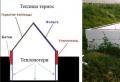
When renovating a bathroom, many install a heated water floor system. These devices operate on the same principle and on the same media as central heating. Often the general installation diagram looks like this:
- heating device;
- high temperature heat exchanger line;
- low temperature radiator circuit.
The heating radiators receive water heated by the boiler. Usually its temperature is at least 75 degrees. However, the flooring surface does not provide heating above 31 degrees. A greater value will cause discomfort to a person when walking on the floor barefoot. However, taking into account the thickness of the concrete solution in which the pipes are embedded and the finishing layer, the total heating of the coolant entering this circuit should be no higher than 50 degrees. Therefore, hot liquid from the heating device cannot be directed directly into the heated floor circuit. It is for these purposes that a collector for a water heated floor is needed.
A manifold for a warm water floor mixes boiling water from the system with cold return water and directs the heated liquid into the heating pipes
In this device, hot liquid from the heating line is mixed with cold liquid from the return circuit. As a result of this process, a carrier of the required temperature enters the floor heating system. At the same time, the entire structure works properly and smoothly. From the boiler, the hot coolant flows directly into the batteries and collector. The cold return line is also connected to the mixing unit. At the outlet of the unit, coolant heated to the required temperature flows into the floor heating system.
Sometimes you can arrange heated water floor without collector. In this case, a common low-temperature circuit is installed for both systems, and heating of the media in them is provided by an air pump and controlled by special sensors.
However, if the heating scheme also provides for heating water for domestic needs, in this case there is no way to do without a mixing cabinet. Since such a liquid at the outlet should be no colder than 65 degrees, and this value is too high for floor heating.

Assembling and connecting a mixing unit is a feasible task for everyone
Despite the apparent complexity, install and connect a heated floor collector with your own hands – quite a feasible task. To do this, you need to study in more detail the principle of its operation and the features of the device.
The mechanism of operation of the unit
The mixing device performs not only the functions of regulating the water temperature in the line. He is also responsible for its normal movement along the chain. The device includes a safety valve and a circular injector. The last element ensures normal circulation of the media in the floor heating system at the required speed. This moment is important for complete and uniform heating of the surface.

The circulation injector is responsible for the uniform distribution of warm media in the water floor circuit
The safety valve is responsible for mixing the water in the circuit. When boiling water enters the inlet, it opens flows from the return circuit until the hot water is mixed with the cold carrier from it. After this, he stops supplying boiling water.
In addition to the two main components, the manifold may include conductive and shut-off valves, valves for bleeding air and a bypass, which serves as an overload protection device. These items may not always be included in the device. Therefore, a do-it-yourself manifold for a heated floor can be installed using several different methods. Here everything depends only on the result you need.
It must be said that the mixing unit is always mounted in the area before entering the heating circuit. However, its immediate location can be anywhere. In some cases, it is advisable to install the device directly in the same room where the system runs. This is usually done in apartment buildings. Sometimes it is appropriate to place it in a common boiler room. This option will probably be preferable for private cottages. If there are several rooms with underfloor heating, distributors are usually placed in each of the rooms or one common manifold is installed in a suitable location.

When installing the mixing unit yourself, draw up a diagram of its installation
All differences in the operating principle of mixers are determined by safety valves. The most common of them are valves with two and three positions.
Supply valve
The valve has two positions, or two-way, and is equipped with a thermocouple. It is this part that has a temperature sensor and controls its level before being fed into the floor heating circuit. This element opens and closes the valve when boiling water is supplied from the boiler or boiler.

Two-way valves are the best option for equipping a heating system for a small living area
Often, access to cold water is constantly open, and hot liquid is supplied as needed by a safety valve. This helps protect pipes from overheating and extends the life of the entire system. In addition, the supply valve does not allow large amounts of coolant to pass through. Therefore, the water in it mixes evenly and heating occurs gradually, excluding temperature jumps.
In most cases, such a device will be the best option for installing heated floors in rooms up to two hundred square meters.
Three position valve
This device combines the functions of a supply valve and a balancing valve. It differs from a two-way valve in that the mixing of liquid inside this device occurs constantly.

In systems with three-way valves, sudden changes in coolant temperature cannot be excluded
The valve is designed so that in its reservoir between the supply of boiling water and cold water there is a valve, usually installed in a position of 90 degrees. However, it can be turned in one direction or the other, depending on the temperature you need. Control and adjustment are carried out in them using a servo drive and temperature control sensors. You cannot do without such devices if there are several heat-conducting circuits in the house. In addition, these devices are suitable for weather-dependent heating systems.
Such equipment allows you to change the degree of heating of the pipes depending on the outside temperature. When it decreases, the efficiency of the previous heating will no longer be so high. Therefore, automatic adjustment occurs according to the specified parameters. Although there are manually operated devices, they are ineffective. Today, automatic three-way valves have gained particular popularity.
In these devices, the weather controller calculates the desired temperature and controls the valve. The equipment is a 90-degree segment, divided into twenty equal sections of 4.5 degrees. Automatic temperature verification occurs every twenty seconds. If the specified parameter does not correspond to the actual heating of the medium, the device moves the value in the desired direction by one division, that is, by 4.5 degrees.
In addition, such devices can save on energy. In your absence, you can pre-specify the minimum required degree of heating and the automation will maintain it.
For all their advantages, three-position valves have some disadvantages. During their operation, the accidental possibility of boiling water being released into the underfloor heating system cannot be ruled out. Such situations are unacceptable, since due to a sudden change in temperature, the pipes may not withstand such surges and burst, which, in turn, will lead to other troubles. In addition, unlike supply valves, these mechanisms have a high throughput. Therefore, it is quite difficult to adjust it. Even minor changes in this case can lead to a sharp change in the temperature of the carrier in the line.
Location of collection departments
As noted above, you can place a mixing unit for a heated floor with your own hands in front of each of the heating systems or install a common manifold. In the first case, each group must be equipped with temperature regulators, flow equipment and the following valves:
- Return balancing valve. This device sets the required heating level for the floor heating system. Inside it, the flow of boiling water and cold media from the return system is regulated. To turn it and fix it in the required position, use a hex key. The valve is finally clamped with a special fastening screw to avoid accidental displacement of the valve from the specified parameters. In addition, the device has a flow scale that regulates its throughput. It is usually limited to five cubic meters per hour.
- Radiator balancing shut-off valve. This device serves to connect the collector section with the rest of the heating system circuits and performs regulatory functions. To install it in the required position in the same way as in the first case, use a hexagon and a clamping screw.
- Overflow valve. This device maintains constant pressure in the system by continuously pouring excess coolant into the bypass. This property distinguishes it from a conventional safety valve, since the latter regulates the pressure by releasing liquid once. The parameters necessary for the normal functioning of the heated floor are set using a special control handle.
Installation diagrams for heating systems may vary. For example, for a circuit with one radiator pipe, a bypass must be provided. At the same time, it must always be open so that excess boiling water flows directly into the radiator. If a return circuit is also provided, then there is no need for a bypass.

Manifold installation diagram in the absence of return
If the total heated area is small, it is advisable to place the collector compartment on the secondary circuit.
The assembled mixing unit is often placed in a manifold cabinet specially designed for this purpose. Remember that it should not be too far from the floor heating system. Although it is allowed to be placed in a common boiler room, and not just in a heated room.
It should be mentioned that all the elements of the collector can not only be assembled independently, but also purchased ready-made. Considering the complexity of calculating all devices, it is better to entrust this stage to specialists. After installation and connection, do not forget to test run the heating. In this case, pay attention to the degree of heating of the floor and its uniformity. Proper temperature adjustment guarantees a successful result.

Layout of the main components for a two-pipe heating system
Installation and connection of the mixing section of the underfloor heating system is perhaps the most difficult stage in the equipment of this heating structure. Such work requires special knowledge and experience to carry out calculations. If you are not confident in your abilities, entrust the job to qualified craftsmen.
8632 1 1
Heated floor manifold - 7 best-selling models
The water floor heating system has long ceased to be a curiosity, but unlike the radiator version, it requires fine tuning, and the manifold for the heated floor is responsible for this tuning. Let's take a look at the main functions of this unit together, plus you will learn how to assemble the system, and for those who are already selecting a manifold, I will tell you about the 7 best-selling models.
Purpose and operation of the collector block
Many people believe that the collector unit is just combs and install models according to the principle “why pay more”. But do not forget that most heated floors are installed in a concrete screed and in case of an error, correcting the situation will be quite problematic.
What is a collector?
First, a small educational program: the maximum coolant temperature of a water heated floor is 40ºC; if it rises, it will be uncomfortable to walk on such a floor. The average boiler produces coolant with a temperature of 70–90ºС, and to lower it, and at the same time distribute it along the circuits, a collector unit is used.

The simplest manifold is a distribution unit of two combs with a pump, one at a time supplies hot water to the circuit, and the second is placed on the return line. But with this approach, you will constantly have to regulate the water temperature using the boiler.
It’s good if it’s a condensing gas boiler, where this process is automated, but not every owner can afford such expenses, since this equipment is expensive.
Plus, there is no point in spending a lot of money if you can install a manifold with a built-in mixing unit, and then decide whether you can connect a thermostat and automate the process, or you can regulate the system yourself. But in any case, installing and tuning a collector is several times cheaper than an “advanced” boiler.

Selection of material and connection diagram
As for the material, manifold combs are now made of polypropylene, stainless steel, brass and copper. Stainless steel and brass are considered the best; the budget polypropylene option is relevant for small systems with 2-3 short circuits without high pressure.
Craftsmen familiar with the installation of plastic pipes solder combs from polypropylene fittings. A homemade manifold is relatively inexpensive, but there are a lot of solder joints that very often begin to leak, so I advise you to buy solid-cast factory models, even if they are plastic.
The simplest connection diagram is direct, that is, directly from the boiler to the combs with a pair of intermediate valves and a circulation pump. But from experience, everyone who installed it, after a year, converted everything to an adjustable design with a two-way or three-way mixing valve.

A two-way scheme in a standard private house is considered the most optimal option. It is easy to set up and works flawlessly.

The three-way mixing valve is only used in heated floors with a coverage area of at least 200 m². If it is connected in small areas, interruptions in operation and uneven heat distribution are possible.

General installation rules
Usually, owners try to install the distribution block with all the accompanying equipment in a special cabinet, it’s more convenient, but you can do without it:
- Assembly begins with attaching the load-bearing reinforcement to the wall;
- Next, distribution combs are screwed to this fitting. They should already have coolant flow sensors, valves and regulators;
- The sizes of the combs also play a role; if you have more than 8 circuits, then instead of one large one it is better to install 2 small combs: for the supply and for the return. With this approach it will be easier to regulate the system;
- Now we connect the supply and return pipes to the combs. Installation of circuits and piping from the boiler should already be completed by this time;
- The last to be installed is the circulation pump, servo drive, valve and thermal head, after which the system is connected to the boiler.
Remember - first the system must be completely assembled, launched and driven for at least 1 day. Only after this can the underfloor heating pipes be filled with concrete screed.
Seven most popular models
| Illustrations | Recommendations |
 |
Model No. 1: LUXOR.
The Italian brand LUXOR produces reliable brass equipment.
|
 |
Model No. 2: GIACOMINI.
Another bright representative of Italian quality.
|
 |
Model No. 3: ARS.
These Turkish-Italian manifolds are of excellent quality at a reasonable price; such equipment can be called the golden mean.
|
 |
Model No. 4: FADO.
The company itself is Italian, but now they have begun cooperation with APC and the products can be declared as joint production.
|
 |
Model No. 5: BIANCHI.
The technical characteristics of the Italian collector BIANCHI are similar to its Italian counterpart from GIACOMINI. The only difference is the number of circuits and price. |
1.
2.
3.
4.
It is accepted that the installation of a heated floor collector begins with the arrangement of a niche in the wall where it is supposed to place a cabinet for it. The dimensions of this special box are usually 60x40x12 centimeters. The place where the distribution manifold for heated floors is mounted should be located directly next to the surface of the floor covering.
The need to install a manifold cabinet
The cabinet in which the manifold for heating and underfloor heating will be located, shown in the photo, is necessary to hide this element of the heating system. It is also the place where heating pipes are connected to other structural parts for heating the premises. Devices for regulating the supply of coolant and the functioning of the heated floor are also installed here.Some owners of private houses prefer to install a manifold for underfloor heating with their own hands. After the special cabinet is ready, the coolant supply and return pipes are installed into it. The first of them supplies hot water to the system from the boiler, and the second collects the cooled coolant and returns it back to the place of heating.
To ensure that the movement of water is continuous, perform. Shut-off valves are installed at the ends of the supply and return pipelines. Thus, if it is necessary to turn off the heating in one of the rooms or in a certain part of the building, you need to close these two taps, which will not affect the heat supply to the rest of the rooms in the house. To connect a plastic pipeline to a metal valve, a compression element is used - a fitting.
Collector as an element of the heating system
The valves must be connected to the manifold. It is a piece of pipe that has several outlets on one side. The collector input must be connected to a valve. Using special fittings, the heated floor collector is connected to the metal-plastic heating circuits of the heating system.
A distribution manifold with several branches has an outlet at the opposite end of the pipe. It is closed either with a regular plug, or a splitter is installed - it has a drain valve on one side, and an air vent on the other, which automatically removes air accidentally formed in the system.
Both pipelines are arranged in a similar way - both the supply and return directions. For this reason, when installing a manifold for a heated floor with your own hands or a team of specialists, the comb and other necessary parts are purchased in pairs.
A warm floor and heating manifold is installed, taking into account the location of the main pipe system intended for the heating boiler, and the configuration of the pipelines to provide heat to individual rooms. It is advisable to have it performed by an experienced specialist.

As a rule, a do-it-yourself heated floor collector is mounted in a wall space in such a way that its location is equidistant from the end points of the heat pipes. Thanks to this, it is possible to ensure optimal operating conditions for the heating system. In the case when heat supply is necessary for a large number of rooms and utility rooms, it is advisable to provide in advance several distribution units for the coolant liquid (read also: "").
Installation of a warm water floor, detailed in the video:
Components of the collector group
The collector group for heated floors includes:- comb-pipelines, which represent tees connected according to the “TTT” scheme;
- mixing unit with three-way valve;
- supply manifold with control valves for water flow to the branches;
- return manifold - adjusting valves operating in automatic mode with a servo drive;
- a circulation pump having a drainage device;
- devices for and automation of the heat supply process.

As the connection diagram for the underfloor heating manifold provides, the hot coolant enters the mixing unit for the water heating system, in which the supply and return water are mixed to ensure the heat supply mode (read also: " ").
The fittings installed on the combs are responsible for supplying a heat source to the individual circuits of the mounted system and at the same time controls the design of the heated water floor. When a certain (set) temperature in the room is reached, automatic valves block the access of the coolant liquid to the heating circuits. A manifold for underfloor heating with flow meters ensures economical consumption of energy resources.
You can purchase a manifold for a warm water floor as a complete set, or each of its parts separately. When the decision is made to install a collector group, it should be remembered that the pump unit must be equipped with a drain valve to ensure drainage in one of the sections of the heating system. In addition to the drainage device, the collector must have an air exhaust system installed at its highest point.
In addition, comb-pipelines must be equipped with special indicating and measuring devices, such as pressure gauges - thermometers, pulse devices connected to heating sensors in the screed.

Particular attention should be paid to the correct installation of the collector unit for a water floor heating system - how warm and cozy it will be in the house depends on its operation (read: " "). Before connecting the underfloor heating collector, it is necessary to complete a detailed layout of all elements that provide heat supply and carry out installation in accordance with the plan. Otherwise, eliminating the shortcomings will cost a significant amount.
After completing the installation of all elements of the manifold cabinet, a test run of the system is performed in order to detect errors and defects. The operating pressure in it should be approximately 25% higher than this figure required for continuous operation.
Independent design and installation of heated floors is a responsible undertaking that requires a competent approach. It is very important for all those who have decided to independently install a manifold for a heated floor with their own hands to take into account absolutely every nuance and trifle that is insignificant at first glance, otherwise in the future the efficiency and performance of the entire heating system will be a big question.
In addition to the fact that the owners of the premises need to take care in advance about choosing the material of the pipes and drawing up a diagram of their location, it is very important to ensure that the coolant is evenly distributed throughout the entire system. It is for these purposes that a collector is installed, the main purpose of which is to preserve and maintain a given heat balance in the system.
So what is a collector?
Considering the fact that for the normal functioning of the entire water heated floor system, it is necessary to provide in advance for the presence of several entry points for the coolant, it is recommended to initially plan how exactly it will be distributed throughout the system.

As a rule, the collector assembly includes two combs, through one of them the liquid is supplied from the heating system to the pipes installed for the heated floor, and the other is designed to combine the return flows of the cooled coolant.
The most popular collector schemes
The underfloor heating manifold is one of the key components of the room heating system. In technical terms, it is a separate group of pipes assembled according to a certain pattern, allowing the combination of several water flows into one.
In practice, three pipe connection options are most often used:
- Parallel circuit of mixing branches;
- Sequential circuit;
- Combined connection type.
How to choose the most optimal one? When using a parallel circuit for connecting coolant branches, a portion of the thermal energy is often lost. Its use is due to the fact that it allows the installation of a two-way valve, adding a convenient control element to the circuit.
Sorry, nothing found.
The second option has the highest performance compared to all other schemes.
When using a sequential circuit in a home heating system, the consumer has the opportunity to obtain the maximum amount of thermal energy.
In turn, installing a combined connection diagram for a heated floor collector allows you not only to quickly install the entire system, but also to do it yourself, without resorting to the help of specialists.
What determines the choice of collector?
The choice of the most suitable model of equipment of this type depends on the heating floor installation scheme used and the location of the collector. It is important to remember that the design of the collector includes coolants characterized by different levels of heating, which makes this equipment an extremely vulnerable element of a water heated floor. For its efficient and completely safe operation, it is recommended to use components made of high-quality material with the highest strength characteristics.
 Modern collector material is stainless steel.
 Most often, the faucet itself is made of brass, however, recently you can find models made of stainless steel on the market. The final cost of the product will depend on its completeness. If desired, the owner of the premises can either choose very simple options or models equipped with various sensors, drain valves and thermal control units.
No less attention must be paid to the selection of all other components of the heating system - thermostatic equipment and pump, which must be of high quality and absolute reliability. If you plan to install several heating circuits, it is possible to install on each of them its own thermostat and flow sensors. Such a manifold for a heated floor is supplied complete with a thermal probe, a diverter device and a mixing tap; their installation is not difficult and, if necessary, can be done by hand.
 The circulation pump is an important element of the system.
 When servicing several circuits with one collector, the length of one loop should not exceed 115-118 centimeters. If a water heated floor is installed in a small room, it is permissible to use a collector made of plastic and having a simple temperature control system.
In recent years, various control elements have increasingly been added to the design of underfloor heating collectors, which allow them to be used not only as a distribution system, but also as a full-fledged control point for the entire heating system of a room. The simplest option would be to use a scheme that provides in the design of the collector, in addition to the common pipe, also control valves.
 Manifold control valve.
 Such solutions are perfect for heated floors with water circuits of different sizes. Having decided to install such a warm floor collector, it is necessary to provide in advance the possibility of mechanical adjustment of each shut-off valve, which allows you to obtain the most acceptable results at the output.
A more efficient design of the device will be a design that ensures the automatic operation of the collector, the operation of which will change depending on the current temperature of the coolant. You can see similar devices in the illustrative photos in the article. Such schemes can include a large number of different elements.
 Device diagram.
 The hot water inlet system is designed to distribute fluid evenly throughout the system. For all those who plan to independently install a manifold for a water-heated floor, experts recommend installing each inlet with its own control valve. Even an ordinary homeowner who is not used to doing anything with his own hands can cope with this task.
A return manifold into which cooled liquid will flow from the pipes of the floor heating system.
A balancing flow meter, which will act as the main control mechanism to ensure uniform flow of coolant throughout the water circuit.
 Temperature sensor.
 Exhaust valve designed for emergency air release. It is indispensable when the pressure in the pipes increases excessively. Temperature sensors that allow you to monitor the temperature of the water in the system. It is important to remember that the maximum water heating allowed in water-heated floor pipes is 55°C.
A circular pump will improve the efficiency of a water heated floor. The pump increases the speed of fluid passage in the system and is responsible for mixing warm and cold coolant.
Each of the elements described above is very important for the entire warm water floor system. That is why it is necessary to pay as much attention as possible to their selection and subsequent installation.
Benefits of using a collector
As practice shows, the use of a collector in a water heated floor system has a number of undeniable advantages, such as:
- Safety – the end consumer of thermal energy is completely protected from mechanical and thermal injuries;
- Hygiene and environmental friendliness - eliminates the possibility of bacteria, mold and fungi;
- Durability and the highest performance characteristics - with proper installation of the collector and compliance with all the basic rules for its selection and installation, the heating system will faithfully serve for at least 50 years;
- Economical - the ability to control the temperature in the system saves up to 50 percent of thermal energy consumption.
It should be noted that independent installation and connection of a water floor collector, in principle, should not raise questions even for a person with a minimum set of theoretical and practical construction skills. The main thing here is to strictly follow the recommendations and instructions of specialists and choose the right product components.
Installation work
When carrying out self-assembly and installing a heated floor collector with your own hands, it is very important to choose the right place; the appropriate video instructions will help you choose it.
For safety, it is recommended to place the entire collector structure in a special protective box, access to which must be completely free.
As a rule, the distribution point is placed in the wall space at approximately the same distance from the end lines, thereby ensuring the maintenance of the specified hydraulic mode during the operation of the system.
 An example of a house heating system with a heated floor collector.
 If it is not possible to fulfill these conditions for one technical reason or another, it is necessary to install two collectors, the heat load between which will be distributed evenly.
Cabinet Installation
Quite expectedly, it does not have sufficient aesthetics, which is why most owners of residential premises prefer to hide it in a special cabinet, which also performs protective functions. In principle, you can make such a cabinet with your own hands, or you can purchase a ready-made one, which will have all the necessary openings for the outlet and inlet pipelines. Installation of such cabinets does not take much time and requires a minimum of knowledge and skills. The edges of the supply and return pipes are inserted inside the protective box, and special shut-off valves are installed at the inlet openings.
 Manifold cabinet with lock.
 The cabinet is attached to the wall surface using small holes in the body. Depending on the type of construction, options for fixing the box to a vertical plane may differ in some specific features.
Installation and connection
To properly install manifolds for heated floors with your own hands, it is very important to have at least theoretical knowledge about the structure of the heating system at home. As mentioned above, the entire design of the system consists of two lines of pipes connected to each other. One line is designed to regulate the pressure of warm liquid, and the other is designed to remove already cooled water from the system.
After selecting and purchasing a collector, you need to install it in a cabinet prepared in advance. The final and most critical stage of the work will be connecting the collector to the general heating system. To do this, shut-off valves are installed on each pipe in the heated floor circuit, which allow, if necessary, to turn off the heating of the room from the general house system. It is important to know that absolutely all underfloor heating manifolds must be equipped with shut-off and control valves, which will allow you to completely turn off the water circuit or manually change the volume of coolant flow.
It is an integral part of the auxiliary or main underfloor heating system. Its design, assembled according to a complete professional scheme, is quite complex, as it consists of many interdependent elements. However, in many apartments, small private cottages or country houses, the heating system is equipped according to a lightweight scheme. It can contain only a few radiators and two or three TP circuits, which makes it possible to install them in a common cabinet with a simplified manifold (comb). Thus, in most cases, assembling a manifold for a heated floor with your own hands is quite feasible. And setting up such a system will not cause any particular difficulties.
What is required to assemble the main distributor for the TP?
The varieties, configuration and purpose of individual node elements of collectors have already been described in the article “”. Therefore, here we briefly recall that for assemblies of its various types you will need:
- a pair of basic combs (monoblock or composite) for supply and return of coolant;
- two-way ball valves. Two of them will be required to cut off the flow and return from the primary (radiator) heating circuit. The rest can be used as shut-off valves at the inlet/outlet of underfloor heating circuits into the corresponding comb;
- manual valves - rotameters for balancing the coolant flow in each branch. They are usually mounted on the supply manifold for each TP circuit;
- thermostatic valves, manual or controlled by a controller with servo drives;
- a circulation pump, which is advisable to purchase as part of a ready-made mixing group, together with connection taps, a bypass, a mud filter, etc. It should be noted that when installing a manifold for a heated floor with your own hands using a simplified scheme, you can do without a pump, using only an automatic three-way valve or two-way valves like Unibox;
- control devices – pressure gauges, thermometers;
- security groups;
- fittings and various connecting elements for attaching underfloor heating pipes to collectors, etc.
Design of a collector unit
A pre-designed diagram will help simplify the assembly of the comb. Having even an amateur sketch at hand, you will already be insured against many editing mistakes. But a well-thought-out diagram of a heated floor collector, drawn up by a professional, should already take into account a number of parameters and practical aspects. The most important among them:
- number of heating branches (loops);
- determination of characteristics of consuming devices - diameter and footage of circuit pipelines, as well as hydraulic losses in them;
- type of heating boiler, its main operational capabilities - thermal output, circulation pump power, coolant heating temperature;
- the presence of additional equipment in the heating system - storage and damper tanks, pressure gauges, thermometers, safety groups, hydraulic arrows, etc.;
- the need to provide for the possibility of scaling - connecting additional circuits, improving the control system - installing automation devices on existing control elements, as well as units that provide remote access.
IMPORTANT! A professional connection diagram for a heated floor collector does not just give an idea of which tap is responsible for a certain area. It allows you to place the pipelines in a more orderly manner, and in the future facilitate the setup and management of the heating system.

Choosing a place to install the TP manifold
It is very important to determine the optimal location where the underfloor heating collector will be installed. It is desirable that it be located in the geometric center of the building at an equal distance from the main consuming circuits and the heating boiler. Of course, in practice it is impossible to maintain the exact distance from the comb to the heating loops. And the loops themselves rarely have the same length, which leads to an imbalance in their hydraulic resistance. As a result, the coolant will tend to circulate in a short branch, and long ones may result in a lack of flow. And although this problem can be eliminated by installing rotameters or adjustable valves, one should still strive to achieve symmetry in the laying of pipelines.
When choosing a place to place a collector for heated floors in standard apartments or small cottages, you have to take into account the features of their layout. Since the manifold cabinet is not the smallest in size, in conditions of limited living space it is usually located in a closet or in a wall technological niche. However, if the house is larger and already has a separate boiler room, then the distribution combs with all the piping are placed directly next to the heating boiler. In large houses with two or three floors, it is even easier to maintain a geometric mounting center. In them, the collector can be installed in the space under the stairs.
Manifold cabinet
Its presence in the equipment set does not at all affect the functioning of the water heated floor system. However, the collector (installation) cabinet is responsible for the aesthetic component of the perception of the thermal installation, as well as for the safety of its components and their settings. It protects the system's controls, some of which are quite sensitive to external mechanical influences. Sometimes the material itself, for example, a polypropylene manifold, despite all its reliability, can be damaged. Considering these factors, it is recommended to choose boxes with lockable doors.
The mounting height of the mounting cabinet is selected based on local conditions and the wishes of the owner of the facility. It is not strictly regulated by regulatory documents. It should be taken into account that placing combs lower than 50 cm from the floor level is undesirable. The recommendation is due to the practical convenience of supplying pipes for connection and fastening to the manifold. The optimal mounting height for the cabinet is about 1 m.
![]()
TP manifold assembly
Assembling and installing a manifold for a heated floor, purchased as a complete set, according to the instructions supplied by the manufacturer, will not be difficult even for inexperienced home craftsmen. In this case, the most crucial point is to control the tightness of the interfaces of elements and assemblies. And since in factory kits most of the unfinished connections are provided on rubber or silicone gaskets (in rare cases on fulente), this task can be solved quite easily by any installer.
For those who have some experience in plumbing work, it will be more profitable to purchase and assemble a manifold from various elements on their own. By doing this, you will be able to save up to half the cost compared to a ready-made constructor. In addition, it is possible to assemble exactly the configuration that will best satisfy the user’s needs.
DIY polypropylene manifold
Polypropylene manifolds are among the most affordable. However, it should be taken into account that they take up slightly more space than prefabricated metal ones, and even more so. It can also be problematic to install flow meters and other devices for automatic adjustment and control of coolant supply into a polypropylene structure.
The elements for assembling the comb can be fittings used in heating or water supply systems, or finished, factory-cast products. In the latter case, the manufacturer sets a fixed number of taps, which cannot be increased on the selected model.
IMPORTANT! It is more convenient to use a manifold assembled from polypropylene fittings if its design is installed in a boiler room, boiler room or other technical room. After all, with a number of heating circuits of 5 or more, the plastic assembly turns out to be too bulky.

Accessories and tools
To completely assemble a polypropylene heating manifold with your own hands, you will need a special mounting soldering iron - for diffusion welding, and from materials and ready-made elements:
- no more than 1 m of polypropylene pipe PN 20-25 without an external reinforcing layer Ø 32 mm;
- 1-2 m of pipe PN 20-25 Ø 32 mm with internal or external reinforcement. This position can be dispensed with if the manifold does not include the mixing unit piping;
- tees Ø 32 mm (in a quantity equal to the number of TP branches) with bends corresponding to the diameters of the transition threaded couplings for connecting circuits;
- transition couplings plastic/metal. It is better to take models with union nuts - American ones;
- Ball Valves;
- balancing valves - suitable for heating radiators.
Build process
A homemade manifold for heated floors made of polypropylene is made as follows:
- A piece of polypropylene pipe without external reinforcement is soldered to one of the inputs of the Ø 32 mm tee. Its length depends on the skill of the installer. If you are good with a soldering iron, then 5-7 cm is enough - 2 cm per landing depth of the pipe entering the tee and 1-3 cm between adjacent fittings. But they can also solder closely.
- A plastic/metal adapter with pipe thread or American thread is soldered to the lower branch of the tee. These steps are repeated until the number of taps is equal to the number of heating circuits (possibly +1 in reserve). It is necessary to make two such combs, because one polypropylene manifold is intended for supply, and the other for return. However, there is no structural difference between them.
- From the end of the comb, a transition coupling is soldered onto metal of the appropriate diameter. Subsequently, a ball valve will be connected to it to block the general supply of coolant to the TP system (if necessary).
- A tee (or just an elbow) is installed at the opposite end to connect the air vent.
- After assembling the polypropylene comb structure, shut-off valves or control valves are screwed to the adapter couplings, and an automatic or manual air vent is installed.
IMPORTANT! It is better to try to weld the plastic fittings of the tees close to each other. Otherwise, the already rather large design of the polypropylene manifold will take up an even larger volume.

The simplest model of a homemade plastic distributor is made in a similar way. If you plan to install various service and automatic devices, then you should provide for soldering the appropriate fittings for them. For example, to install flow meters, it is necessary to replace the tees on the supply comb with cross parts made of polypropylene. In this case, both branches of each cross are equipped with couplings with metal transitions. A metal (brass or bronze) extension of the appropriate diameter and length is screwed into the upper coupling to install the flow meter, and a pipe is connected to the lower coupling. In this way, a polypropylene floor heating distributor can be equipped with any measuring device, a safety group device or a special type of shut-off and control valves.
DIY metal comb for heated floors
To make metal combs yourself, brass or bronze fittings, tees, fittings, and plugs are used. The general layout and assembly sequence resembles a similar process for a polypropylene comb, which only takes a little longer. This is due to the fact that each threaded connection must be carefully sealed using fumlenta, flax tow or special sealants.
When purchasing fittings and other plumbing parts, you should pay attention not only to their attractive price and shiny newness, but also to the true quality of the material. Firstly, it’s good to understand which manufacturer’s products you will be dealing with. If the seller provides a certificate for his products, that will be absolutely wonderful. Secondly, just by some external signs one can guess whether it is worth getting involved with such a product. So, good factory parts are, at a minimum, heavier than fakes and have thicker walls. The use of thin-walled “Chinese” tees, although it will noticeably reduce the cost of the comb, will critically reduce its reliability. In addition, working with counterfeit goods is quite difficult - low-quality material can crack at any time.
IMPORTANT! The use of high-quality bronze fittings brings a homemade manifold for heated floors closer in cost to a factory product - there will be savings, of course, but very insignificant. If installation of adjustable flow meters using crosspieces is required, then self-assembly of the combs becomes completely unprofitable.

Practical aspects of installing a water TP distributor
- It is better to assemble and install the manifold for heated floors before rolling out the pipelines of the circuits. In this case, one end of the pipe is immediately fixed at the place of permanent connection, then, after laying out the loop, the second is fixed.
- By installing a comb with an automatic air vent at the top point of the system, you will forever get rid of the problem of air venting. If the distributor is located, for example, in the basement, then you will have to install additional valves to remove air somewhere on the hinges themselves.
- Each of the combs must have a slight installation slope (rise to the air vent) to relieve air plugs.
- When choosing a collector assembly scheme without a mixing unit, in which the temperature in the loops is controlled by thermostatic valves (RTL regulation), the length of the pipelines in the heating branches should be taken into account. It has been noted that this scheme works well if the length of the pipe loop does not exceed 50 m for a pipe Ø 16 mm. If the length of the branches is higher, then a heated floor collector circuit with
conclusions
The decision whether to make a manifold for a heated floor with your own hands or purchase a ready-made one should be made based on the level of your installation skills, requests for the comb configuration, as well as financial capabilities. It will be important to consider that:
- if it is necessary to connect 3-5 circuits, and the distribution unit is planned to be located in a manifold cabinet, then it is optimal to use compact metal fittings or ready-made monoblocks;
- for a heated floor system with 5-7 circuits or more, the use of polypropylene combs is economically justified. However, in this case it is better to install them in a specialized room;
- For heating systems that are planned to be controlled automatically, it is advisable to buy a manifold for a heated floor in a complete factory configuration.